r/AskElectronics • • 2h ago

12 VAC Small Transformer?

Post image
10 Upvotes

I bought these online by accident, thinking they were 12VDC, not 12VAC. The listing photos were terrible. Seeking suggestions for small transformer(s), 120VAC to 12VAC, as there are 3 halogen bulbs I want to convert. Alternatively, what happens if I feed them DC voltage, at maybe 6V? Any ideas here?


r/AskElectronics • • 12h ago

Can these old, non-polarized, axial paper capacitors be replaced with those from the second photo?

Thumbnail
gallery
30 Upvotes

r/AskElectronics • • 2h ago

Is this polystyrene 15pf?

Thumbnail
gallery
3 Upvotes

Question in the headline. The second image is blurry but its a size reference next to a potentiometer. Thanks


r/AskElectronics • • 51m ago

Where to connect the output load?

Thumbnail
gallery
2 Upvotes

I have this PCB with SLM6600 IC for charging batteries. I can see the B+ and B- terminals to connect the battery, but where should I connect the load? Should I connect the load directly to the battery?

https://robu.in/product/type-c-usb-lithium-ion-battery-charging-module/


r/AskElectronics • • 19h ago

Does orientation matter in this smd 4-pin tactile switch?

Post image
55 Upvotes

This switch popped off my keypad when I was changing the battery and decided to brush some dust off the pcb.

I was just going to solder it back on but wanted to check if these switches have an orientation. I mean if I put it in rotated 180 deg of original is it going to matter?


r/AskElectronics • • 4h ago

Help to identify this LED driver ic Jy6QB

Post image
3 Upvotes

Found a damaged high power LED lamp and thought about reusing the driver

That's an interesting one - it has an external MOSFET switch and it's likely an APFC driver(no input capacitance after the dbridge). Can't find anything related to that chip

P.S.

I know the traces are damaged, I'll fix that


r/AskElectronics • • 3h ago

Component identification: component from PASCO h/e apparatus

2 Upvotes

In the schematics of the h/e apparatus from PASCO there is this component which is not labeled. I suspect it's a cap but I am not sure; I cannot open the thing up.

Here's the schematic.


r/AskElectronics • • 9h ago

Where can I source CH340C in cut tape packaging?

6 Upvotes

I need 120 Qty. of CH340C USB to UART converter IC in cut tape packaging. I am able to see modules and dev boards on mouser and digikey of this IC but I could not find the IC in loose cut tape packaging anywhere. Small distributors are providing the IC in loose packaging which I do not want. Has anybody tried sourcing this IC in this quantities who can let me know about a distributor?


r/AskElectronics • • 24m ago

Flyback converter works in LTspice (5V output), but my physical circuit outputs 0V. Is there something wrong with my schematic?

0 Upvotes

Hi everyone,

I’m building a flyback converter with a 5V output, using a TL431 and PC817 optocoupler for feedback. I’ve attached my schematic.

The LTspice simulation gives me the expected 5V output, but the actual circuit I built only outputs 0V.

Could someone take a look at the schematic and tell me if there are any obvious mistakes? I’m particularly unsure about the startup circuit, MOSFET drive, and transformer winding connections.

What should I check first to figure out why it isn’t working? Also, what measurements or component details would be useful for troubleshooting?

Any help would be appreciated. Thanks!


r/AskElectronics • • 30m ago

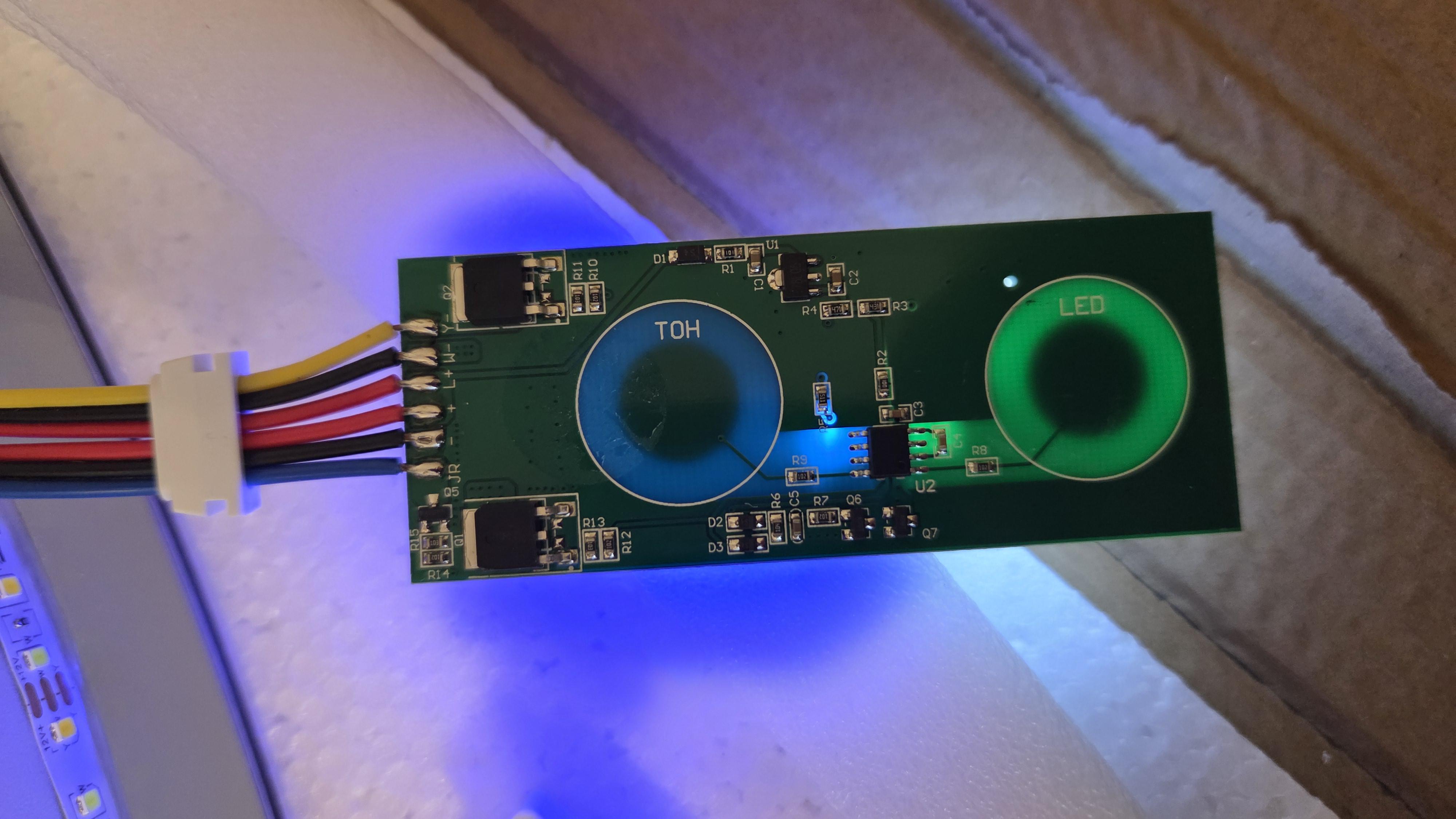
How to interface with this led controller with capacitive touch buttons?

Post image
1 Upvotes

Hi,

I pulled apart a mirror and it has this controller board and 2 touch buttons on the other side (nothing else remarkable there).

I'm looking to simulate a button press with an esp32. I'm thinking the lines with R9 and R8 would be the signal coming from the buttons. Any guesses how would the touch buttons indicate a press? A low-voltage pulse?

Also, any guesses what the U2 unmarked IC could be?


r/AskElectronics • • 2h ago

Companies that sell round Memory-in-Pixel (MIP) displays

1 Upvotes

I am looking to build a smart watch and am thinking about using MIP for the display, however all of the MIP displays I can find are rectangular or square, does anyone know any companies that sell circular MIP displays ideally ~1.43".
Thanks for your help


r/AskElectronics • • 21h ago

What is this resistor?

Post image
35 Upvotes

Does anyone know the rating of this resistor?

I've plugged the bands into different calculators and gotten different results.

My best guess is (Red, Black, Silver, Gold) => 0.2 ohm 5%

Im guessing it's prob a 5W because it's beefy.

Measures roughly 14.5mm in length.

I'm measuring 2.7k across it while it's in circuit so if it really is 0.2 ohm, I'm assuming it's blown.

Any help would be appreciated, also are there different color codings for different resistors with the same number of bands or am I just dumb?


r/AskElectronics • • 18h ago

First time trying to build a class AB amp, is this decent? Looking for advice.

Post image
19 Upvotes

Don't mind the diode models


r/AskElectronics • • 4h ago

Soldering for switch mod

1 Upvotes

I’m looking to mod my switch that unfortunately isn’t eligible for software modding, so I have to solder a rp2040 to it. I’ve never soldered before but I’ve done basic hardware upgrades on laptops and computers and such so I have a base understanding of electronics.

I was wondering what are like the most baseline tools that I would need and also if there’s a good way to practice before I brick my switch.


r/AskElectronics • • 5h ago

RSMDO-2204EG psu gone bad.

0 Upvotes

I have a RSMDO-2204EG oscilloscope where the psu had gone bad. Turns out, on the primary side of the coil, one of the diodes from the full bridge rectifer shorted, and fried the mosfet switching circuit.

The values on the resistors were burned beyond reading the value and replacing, and im asuming the surface mounted caps and diodes are dead too. I can't find a schematic or replacement board.

Tips?

Primary Side

Secondary side.


r/AskElectronics • • 6h ago

Esp32 s3 usb 2.0 differential pair impedance mismatch

1 Upvotes
The fab stack up (They don't do 4 layers)
Calculated Impedance with the minimum clearance and trace width that fab can do.

I can increase the width of the trace to 1mm and impedance will be near the 90 ohm, but physically I can't break that width from the usb pads. I can't achieve 90 ohm in other way. So would it work with the current 128 ohm impedance? USB 2.0 isn't fast enough to cause a problems I think. All I can do is to make the diff pair as short as I can, and keep GND plane below it intact. What do you guys think?


r/AskElectronics • • 13h ago

Help with repairing tps-l2 walkman

Thumbnail
gallery
2 Upvotes

I've had this walkman for a good couple of years now with almost no issues and some small repairs.

But recently when the unit is tilted in specific angles audio presents some heavy buzzing. My first thought was a short in the sound card (pic no.1) but after resoldering all joints and cleaning the board multiple times, nothing nada zilch. Same result.

Then I discovered that if I unscrew what seems to be a grounding screw that connects the board to the metal chassis (pic no.2 and no.3), the buzzing goes away completely. Would leaving this disconnected be a bad idea? I assume that if the grounding is there it's for a reason. I'm not that good with electronics, but maybe something else is shorting the grounding somehow?

Idk.

Any help would be appreciated 👍.


r/AskElectronics • • 1h ago

Help my controller PCB Design schematic

Thumbnail
gallery
0 Upvotes

Completely new to pcb designing and decided a controller was the best starting choice. Making the schematic by hand purely and from scratch and ran into the classic power button issue.

Came across soft latch power switch circuits, and Claude gave me this as an example. Wanna understand before implementing this.

I understand the fundamentals of this circuit design.

- R1 causes voltage drop for P mosfet functioning, if the button is pressed, powering the esp.
-Button pressing sensed by GPIO9.
- Esp sets GPIO3 to 3.3v through firmware, causing N mosfet to function, resulting in two current paths to ground.
- Button released would now still mean one current path to ground, so R1 still does its job.

My doubts are -
Whats the use of D1 and D2, and would the circuit work without them?
Is the R2 function , a pull down resistor?
And how does GPIO9 even sense the button is pressed?


r/AskElectronics • • 1d ago

Blown ATX PSU Root Cause and Repair

Thumbnail
gallery
14 Upvotes

Hello! I've recently started reviving/restoring an old workstation. It has a 250 W "Mitac" ATX power supply, and since everything looked to be in really good condition, I just plugged said power supply into the mains (kind of stupid in hindsight) and hoped for the best, fully expecting the thing to go bang. And it did!

Now, I know my way around PC hardware but am pretty much a novice when it comes to actual EE and PSUs. I've recapped a thing once or twice and can solder alright, but that's about it, so I wanted to ask the experts in this sub: a) what may have caused the failure and b) whether this seems like something I could attempt to repair (keeping all the dangers of working on PSUs in mind), especially because these particular supplies are getting harder to find. I will never leave this thing plugged in and unattended either way.

I've waited a good while for the caps to discharge and took some photos of the damage (without touching anything, of course). At first glance, it seems like a resistor next to a capacitor blew (although I haven't measured it yet) and left a soot mark on said cap (see pics 1 and 2).

The corner of the PCB is also obviously damaged and has broken out of a retaining bracket in the case, although there don't appear to be any traces there. I also don't know whether this happened due to the bang or was already like this from the get-go (e.g. happened in shipping).

The entire PCB appears to have shifted upward, and there is a burn mark on the heatsink and inside the top of the case, so perhaps the heatsinks are live in this PSU design? If so, it seems likely that the PCB was already offset like this when I powered it on, and that is what caused a short.

Any input is much appreciated. 🙂


r/AskElectronics • • 11h ago

Does touching usb port of any mcu cause voltage regulator to short with ground

0 Upvotes

Does touching usb port of any mcu cause esd to destroy it due to ESD(Electrostatic Discharge)

I have noticed that many of my teammates use board and after which the mcu voltage regulator gets destroyed

We use teensy 4.1


r/AskElectronics • • 21h ago

SMD transistor identification - FN 1A marking from an Aura 150 Integrated Amplifier

Post image
6 Upvotes

The one in the middle with a red dot. It reads FN 1A, is around 3mm x 1mm. It's on a rise board in the power amp section of an Aura 150 integrated amplifier. I've been unable to find a service manual for the amp.

My DCA reads a working one as an NPN Silicon BJT, HFE 142 at IC=5.05ma. Although I did measure in circuit.

Can anyone confirm the original transistor or recommend a currently available equivalent?

Thanks!


r/AskElectronics • • 1d ago

why use transformers for coupling in Radios instead of capacitors?

22 Upvotes

im in the process of building/experimenting with building a Tube radio. but in almost all radio schematics i can find (both tube based and transistorized) they couple amplification stages with a transformer that resonantes at the IF frequency. but why don't they use an LC tank circuit and then couple the output through a capacitor like i've shown in the image. what are the benefits of using a transformer?


r/AskElectronics • • 19h ago

Soldered Xbox pins badly, now won’t turn on

Post image
4 Upvotes

Hello this is an Xbox Corona I was trying to solder an S RGH glitch chip on it after putting on pico to read the NAND using these output pins. I wasn’t able to read a NAND but putting it back together, the Xbox power brick is orange and the LED indicator on button doesn’t turn white. I’m not sure how to diagnose this or if it’s just better to recycle it, does anyone have any tips on what to check/do? Thank you!


r/AskElectronics • • 19h ago

Do I need a new board?

Thumbnail
gallery
3 Upvotes

So I offered to take a crack at repairing a TASCAM DR 40. Initially, the only problem I noticed was there was no line out 3.5mm aux port. Therefore, I found the OEM part number, ordered it, and now I am trying to solder the board. I tried to solder it in, but I stoped when I realized I that some dumb sucker had ripped the solder pads off. My questions that: do I need to go purchase a new board or can I somehow unfuck this situation?